Struts were replaced, giving a huge improvement in ride, noise and turning smoothness.
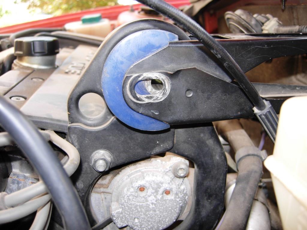
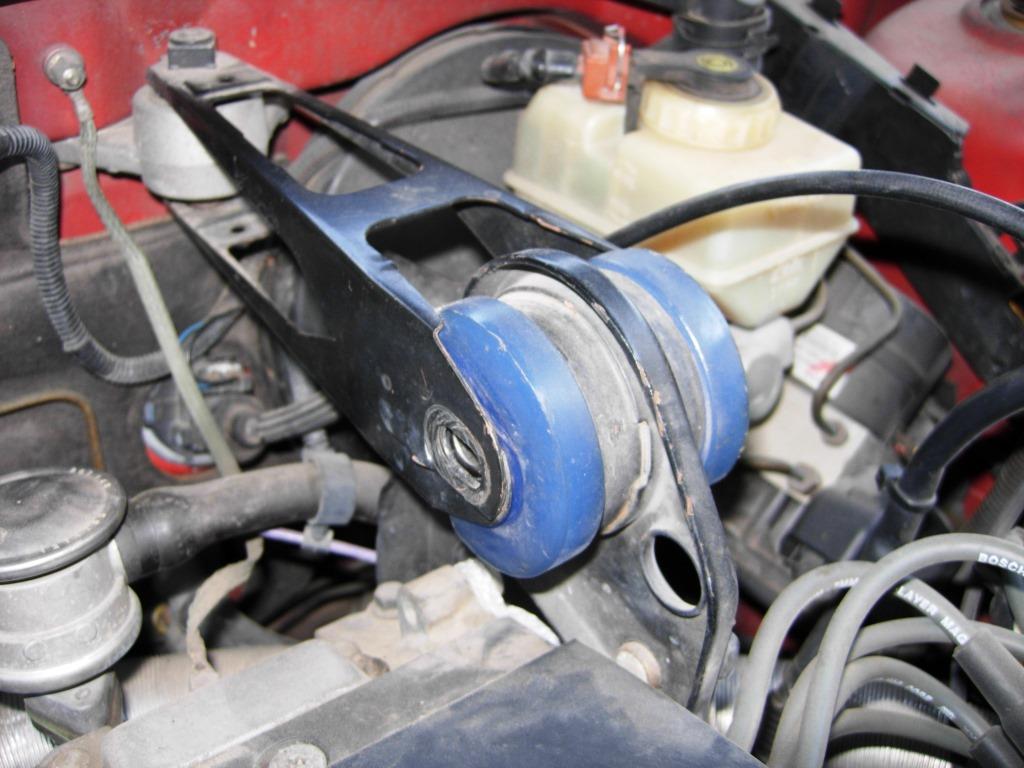
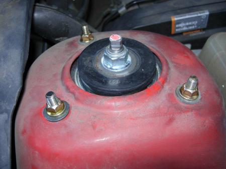
Besides making squeaking noises and a less-than-comfortable ride, the struts needed replacement because the spring seat on the right side was failing. The rubber seat where the top of the strut spring sits is a well-known failure item on Volvo 850s. If you take a wrench to the upper nut and turn it, there should be little movement on a good seat and it should quickly snap back to the relaxed position. You can get quite a bit of twisting movement on spring seats that are failing and the nut spins freely when they are torn completely. The nut could twist quite a bit on this car so needed a seat replacement along with the gas shocks and who knows what else in these strut assemblies.

If you can get any real movement out of these nuts at top of strut, the rubber spring seat is failing.
Struts should always be replaced in pairs to give equal ride on both sides, even if only one is bad. In this case the right side strut had a torn spring seat while the left side was rather squeaky. Both really did need replacement.
Started by lifting the front of the car securely on jackstands with the wheels removed.

Strut replacement begins with car on stands and wheels off.
Next is to support the wheel hub with a jack to just take a little load off the strut.

Support the wheel hub so the shock is not extended.
To free the strut for removal involves unscrewing six fasteners in three locations. First unbolt the sway bar link from the strut mount (one nut).

Sway bar link disconnected from strut.
Then unbolt the lower strut from the steering knuckle of the wheel hub (two bolts/nuts).

Strut unbolted from steering knuckle (wheel hub).
Finally unscrew the nuts securing the upper strut bearing mount under the hood (three nuts).

Top of strut (bearing plate) unbolted from under hood allows the strut to drop.
There is also an anti-lock brake (ABS) sensor cable grommet that needs to be pulled out of the bracket on the strut.

ABS sensor cable pulled out from bracket.
The actual sequence here is not important but all four things need to happen to free the strut from the car. Now that it’s free, the support can be removed and the strut can simply be dropped down and removed from under the wheel well. The old struts (not original, but not sure when they were last replaced) were very grimy, worn and torn up.
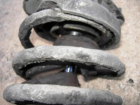
Struts in bad shape.
At this point the strut is typically disassembled with special tools and then reassembled with new parts as needed. The spring is almost always salvaged and the other parts may be replaced depending on condition. It’s generally a good idea to replace everything but the spring.
For this job, however, and this is where many Volvo purists will get upset, I did not rebuild the struts. Instead I bought complete strut assemblies ready to go. This gives us new gas shocks, coil springs, dust boot, bumper, bump stop, spring seat, bearing plate, retaining nut, upper cushion and top nut. The quality of each of these may not be factory level but I’ll be happy if we get five years out of these. I used Gabriel ReadyMount complete strut assemblies (G57040). Three factors in choosing these: 1) Price was unbeatable with the pair running only $250 after instant rebate; 2) Time saved not rebuilding the struts; this cuts my effort down by at least three hours per car; 3) Favorable reports about these struts by certified buyers on their 850s. Volvo forums lean towards factory only parts, or at least high quality after-market level. I have no way of knowing where these complete assemblies fit in to this mix so this is something of an experiment. I will update this post if and when there is an issue with the struts.
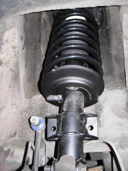
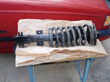
Comparing the old and new strut assemblies is very favorable. The only missing detail is the ABS sensor wire bracket which needs to be screwed onto the appropriate side.

Complete strut assembly matches original perfectly.

Installation of the new strut assembly is straight-forward; just reverse the removal procedure. Orientation of the strut is impossible to confuse as both top and bottom have to be turned a certain way to install. The upper mounting is easy but the lower connection to the steering knuckle takes some effort to line up the bolt holes. As long as you can move the wheel hub around it can be done.

Secure upper part of strut loosely with nuts.
Strut roughly fastened at top.

Strut roughly fastened at bottom.
One extra detail is to screw the ABS sensor cable bracket into the appropriate side. The strut has holes pre-drilled for this and self-tapping screws are provided.

Screwing in ABS sensor cable bracket is easy.
Now it’s just tighten all the fasteners to the factory torque spec. Again, in no special order:

Lower strut secured to steering knuckle.
New fasteners are recommended for the lower strut bolts but I didn’t order any so just re-used the old ones.

Sway bar link to strut nut.

Slip ABS sensor wire grommet into bracket. This takes a bit of forceful massaging.
Upper mounting nuts.
Once everything is replaced and secure on both sides, just put the wheels back on and lower the car and make a test drive. Listen for any unusual sounds and feel how the front of the car rides and steers. For this task the ride was much improved; all the squeaking and popping was eliminated and the turning was smoother. I attribute much of the improved feel to the new springs which give more support than the originals with 17 years of compression on them.
New struts require front end alignment check and adjustment as needed because they alter the geometry of the front wheels, thus affecting caster, camber and toe. Fortunately we purchased lifetime alignment at Firestone so I’ll bring the car in for free alignment shortly.
I dissected one of the struts to see how bad it was and present a short photo essay below.
You need some kind of convenient and sturdy work platform.

Top nut and cushion washer can be removed at any time; these are not under spring compression.

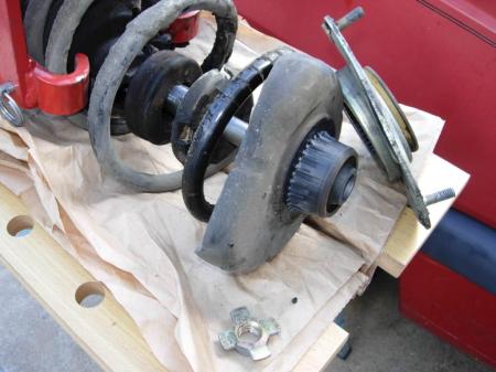
To disassemble the strut further, you must compress the spring to relieve axial force. These two-piece compressors are most common but the cheap ones are scary fragile.

Alternative spring compressor is this massive monster that is sturdy but awkward.

I like the sturdiness of the big red one but it doesn’t clamp the coils as neatly as the two-piece compressor which is less likely to damage the finish (and let the coil rust). So the two-piece ones are probably better for these smaller coils (compared to larger vehicle springs). Just keep a close eye on them in case they show any signs of breaking.

With spring compressed the retaining nut can be removed. This takes a special star-shaped tool and another tool to hold the gas cylinder shaft from spinning.

Retainer nut removed.
Bearing plate pulled out from rubber spring seat nipple. They may have to be pried apart.

Bearing plate in fair shape but bearings were a little rough and worn. Rough bearing reduces steering smoothness.
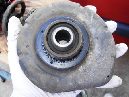
Spring seat, the weakest link in the whole strut assembly. Many folks recommend using a more sturdy part from the XC90 which fits the 850.

You can see the rubber torn in a ring around the shaft sleeve on top…

…and bottom.

Bump stop almost disintegrated.


Shaft protective boot badly torn which lets dirt get into gas cylinder seal and make it slide roughly.

With gas shock removed all that’s left is a compressed spring.
At this point if you were rebuilding the strut you would put in a new gas shock and replace any other worn parts as it is re-assembled in reverse order. There is a starting compression length for the spring that pre-loads the force when you tighten the retaining star nut.
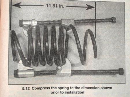
Spring compression length spec when reassembling strut.
It’s also important to observe correct placement of the spring ends at top and bottom on the gas shock and spring seat, respectively.
$250 for two Gabriel ReadyMount complete strut assemblies on Amazon
Technical Notes: Strut assemblies are the primary front end suspension components. The coil spring around the gas cylinder provides the actual suspension of the chassis to the ground while the gas shock absorber provides dampening of the up/down motion for comfort and control. Unlike the rear suspension which has separate shocks and coil springs, these are integrated for minimal use of space. They need to rotate with the wheels when turning so there is a bearing at the top which allows for the struts to pivot with the wheels.